 |
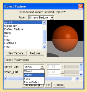
At the
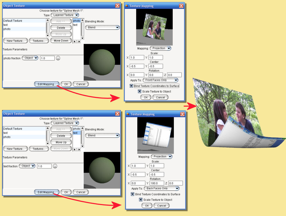
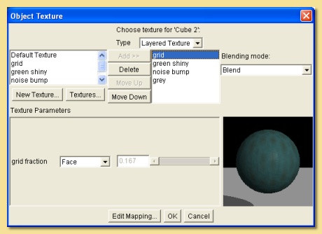
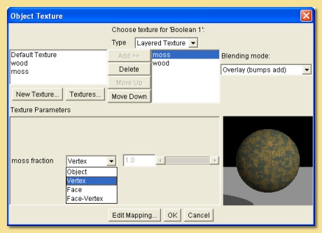
left of the dialogue is a list of all the textures that have
been created in the scene. To add
one of these to the layered texture, select it from this list and click
on Add. This adds the texture to the list in the
centre. This list shows the texture layers and their order is
important. The
topmost layer in this list is the surface layer, the 2nd one is the
next layer down and etc. The order can
be changed by selecting textures and clicking on  . .
Each layer can be one of 3 Blending Modes selected
from the drop-down menu on the right:
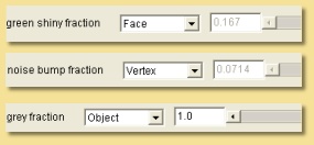
Blend means that a weighted average texture is
created of that texture and the textures below it. The weighting
is defined by the fraction bar to the left of the preview. If this was
set to 0.7, for example, then the
resulting texture would be 70% that one and 30% of the one below. All
texture properties, e.g, diffuse
colour, specularity, transparency etc., are averaged in this way.
Overlay In this case, the current texture is
laid over the ones below with any transparent areas
allowing the textures below to show through and opaque areas will not.
Again a weighting fraction can
be applied which results in partial transparency.
Overlay, Bumps Add is a special version of the
overlay mode where bump and displacement maps sum
through all the layers rather than being averaged or eliminated by
layers above.
|
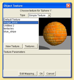
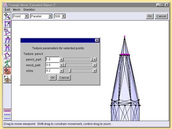
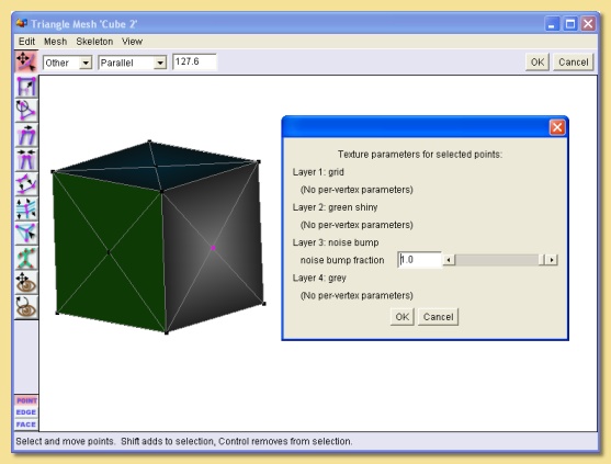
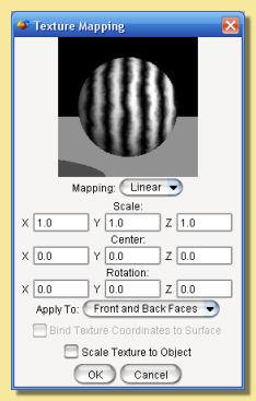
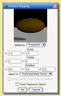
 .The
following dialogue is then displayed:
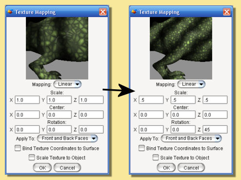
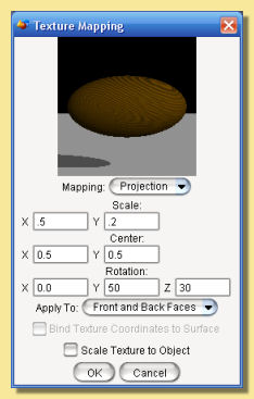
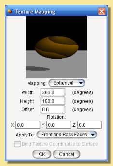
.The
following dialogue is then displayed: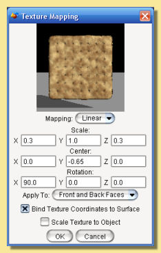
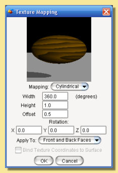
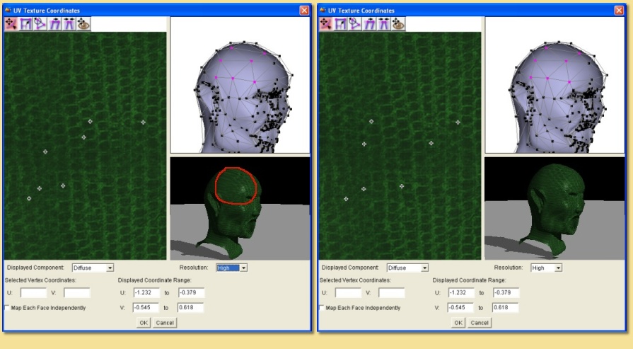
 (hold down CTRL while dragging
to zoom) or by dragging with the right mouse button depressed (again
with CTRL to zoom).
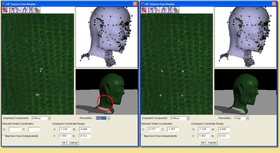
(hold down CTRL while dragging
to zoom) or by dragging with the right mouse button depressed (again
with CTRL to zoom).